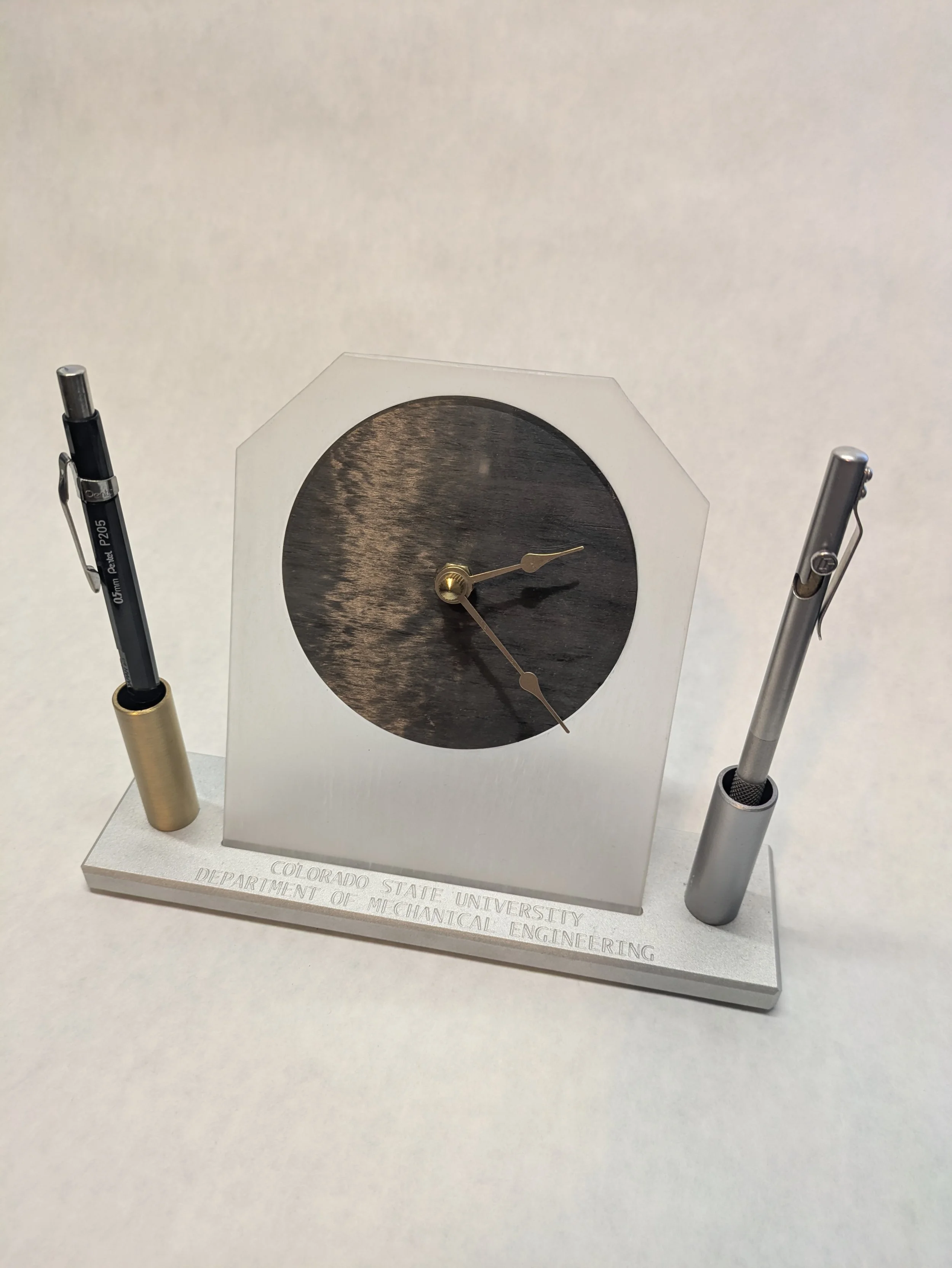
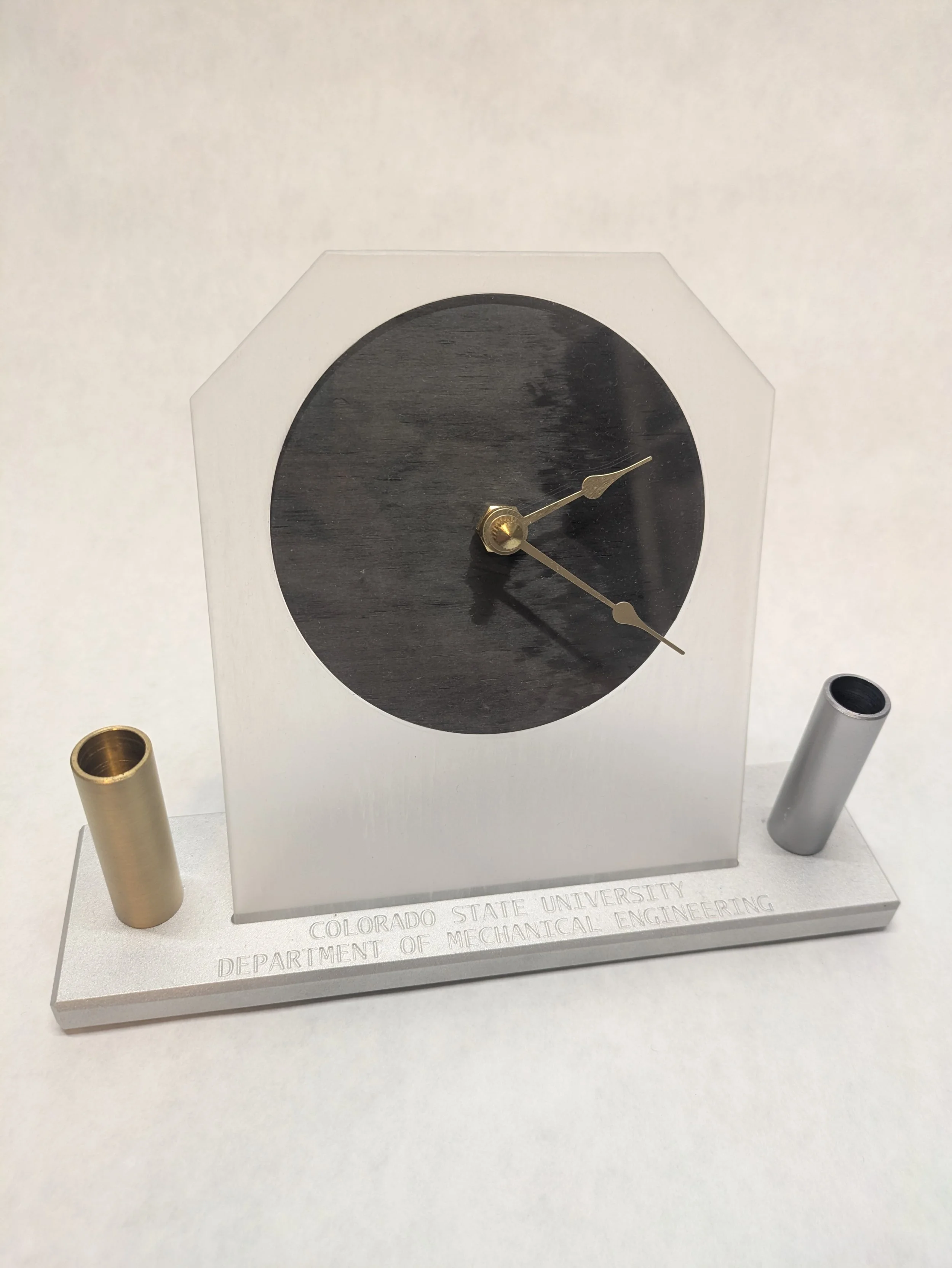
MECH200 Clock Manufacturing Project
Lessons Learned:
Time Management.
That’s the overarching idea between every project I’ve ever designed, worked on, and especially completed.
The clock project gave myself and my classmates an opportunity to experience many different aspects of subtractive machining. From raw stock management to metrology, and many things in between.
- Start early
- Don’t be afraid to ask questions
- If you follow the in-depth process sheet, very little can go wrong
- Don’t be afraid to ask questions
- Leave time for finishing and assembly
- Arrive well rested, sober, and in a good headspace
- DON’T BE AFRAID TO ASK QUESTIONS
Tips for future students
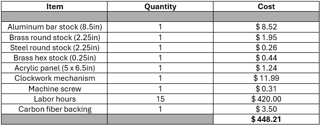
Cost to produce - EMEC process
Improvements in cost - Industrial process
Single stage manufacture: One machine bores all holes for pen/pencil holders, one machine faces to length, etc.
Bulk Purchasing: Can lower cost per unit by 10-30%
Lower machining hours: Time spent is lost opportunity cost, each machine should run all the time
Remove labor costs: By far the biggest cost of the original EMEC process
Increase raw stock accuracy: Less waste for each component yields approximately 5% more usable stock
Industrial cost - 10,000 units
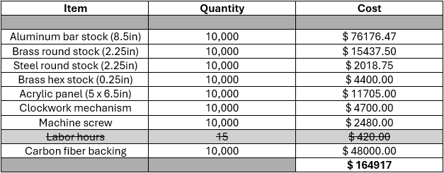
Cost using EMEC process vs. Industrial cost - 10,000 units
The total cost to produce 10,000 units in the industrial process is $ 164,917.72
Compared to over 4 million dollars for the EMEC process extrapolated to 10,0000 units. ( $ 4,482,100 )
The production time would vary considerably as well, each EMEC clock taking roughly 15 hours means that to produce all 10,000 units, the overall time cost would be around 150,000 hours! That’s equivalent to around 14.5 YEARS of full 8-hour shifts.
Conversely, the time to produce a single bored, faced, and threaded brass section can be as little as 2.5 MINUTES. Over all parts of the clock, even if some parts take double (5 min), that’s a single set of clock parts produced roughly every 5 minutes, with assembly taking 20 mins on average for a competent assembler, we’re looking in the order of 1.5 years of full shift work to complete all 10,000 units.
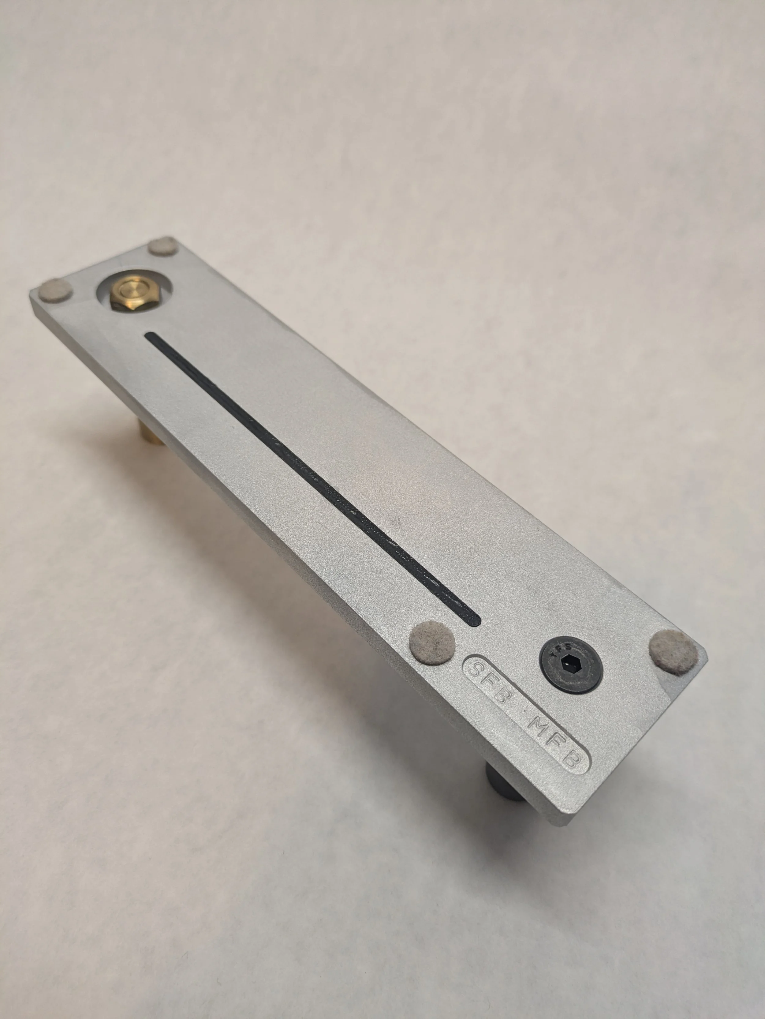
GD&T - Clock Base drawing
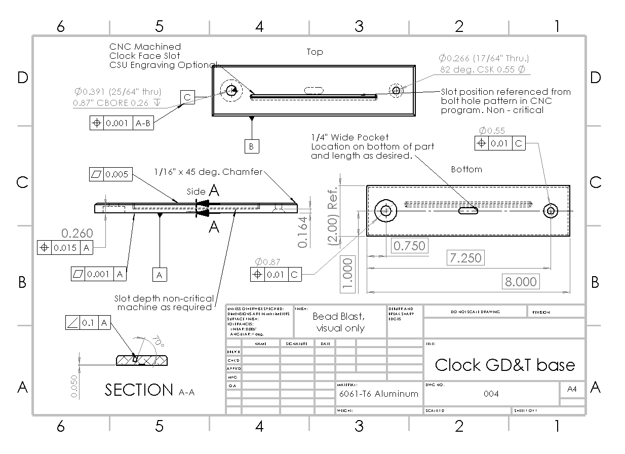
Functional Requirements
Base must sit flat and stable on a surface without rocking
Must support clock face acrylic at the correct defined angle relative to the base
Pencil holders must mate successfully with top surface and seat fully without interference
Spacing across top features must be even and consistent
Edge chamfers must be straight and consistent
Surface finish must be consistent and durable for visible surfaces
Datum A: Underside of base, to prevent rocking and to create an easily measurable surface to work from (primary plane)
Datum B: Front face of base, to define the forward facing aspect of the clock and to create a secondary easily measurable surface to inspect from (orientation)
Datum C: Axis of the left brass pencil holder bore, to define a starting location for the additional features of slotting and secondary bore, as well as the counterbore location (feature reference)
Form control: Flatness on Datum A
Orientation control: Angularity of acrylic supporting face relative to Datum A
Location control: Position of the pencil holder bore relative to Datum A. Position of counterbore relative to Datum C
Surface finish callout: Bead blast to consistent finish, visual only
Straightness applied to chamfered edges